Garmin Emap power adapter housing
This kit allows you to remove the circuit board from your Emap 12V adapter and mount it under a RAM mount, so you don’t need to add a bulky cigarette lighter socket to your bike. WARNING: This modification is an irreversible process! Do NOT proceed unless you are comfortable with soldering circuit boards, and cutting and stripping relatively fine wires. BCE can not be responsible for adapters that are damaged in the installation process. Read through all of the instructions and make sure you understand them before proceeding. E-mail us if you have questions.
Click on the pictures to enlarge.
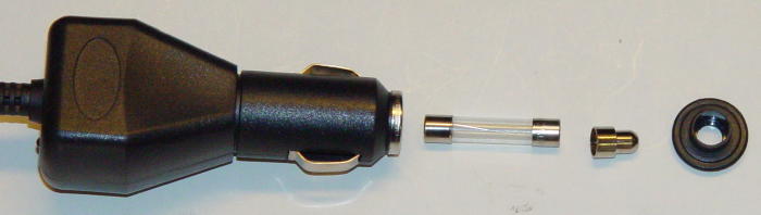
Unscrew the nose of the adapter (this is how you would normally replace the fuse), and pull off the metal ring that holds the two halves of the housing together. Carefully pull the two halves of the housing apart to expose the circuit board.
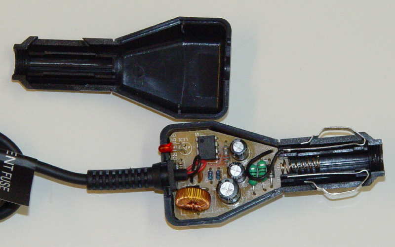
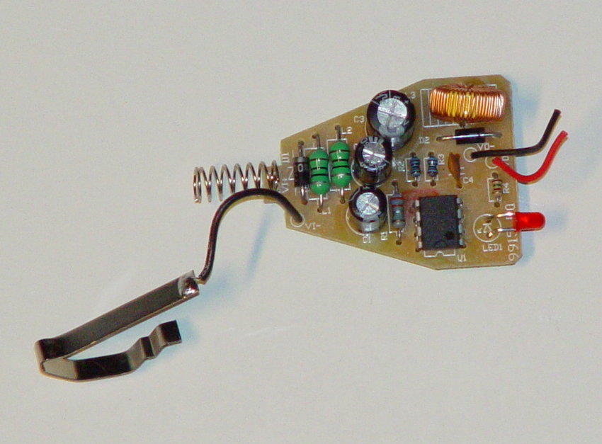
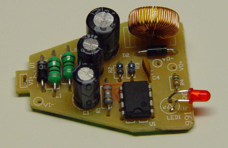
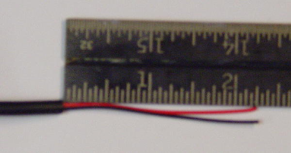
Remove the circuit board from the housing by pulling the cable strain relief from the housing, and the side springs from the nose. Cut the power wires off at the cable. You should wind up with this:
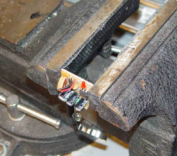
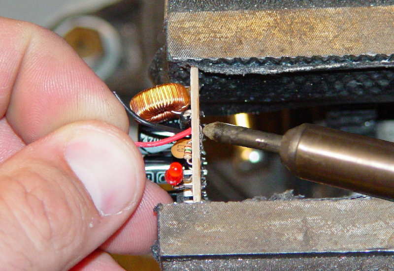
Using the soldering iron, very carefully remove the original power supply wires and spring from the circuit board. It will probably be easiest to hold the board (gently) in a vise, so you can apply the soldering iron to one side and pull on the wire from the other. Be very careful not to apply too much heat to the circuit board; this can cause the copper pads to lift off of the board.
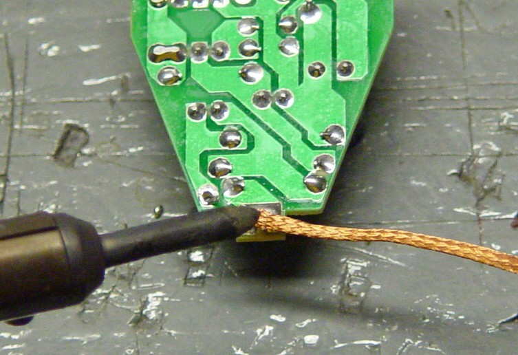
Then, using either solder wick or a spare piece of fine stranded wire, remove the remaining solder from the pads. Do this by placing the wick on top of the excess solder, and heating with the soldering iron. When the solder melts, the solder will be drawn up into the wick. Pull the wick away from the board while the solder is still melted. Cut off the used tip of the wick and do the next pad. It might take more than one application to clear enough solder from each hole.
You do not need to remove all of the solder from the wire pads, just enough to clear the hole and get the new wires through. You should wind up with something like this:
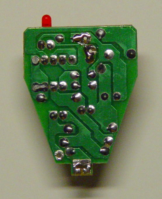
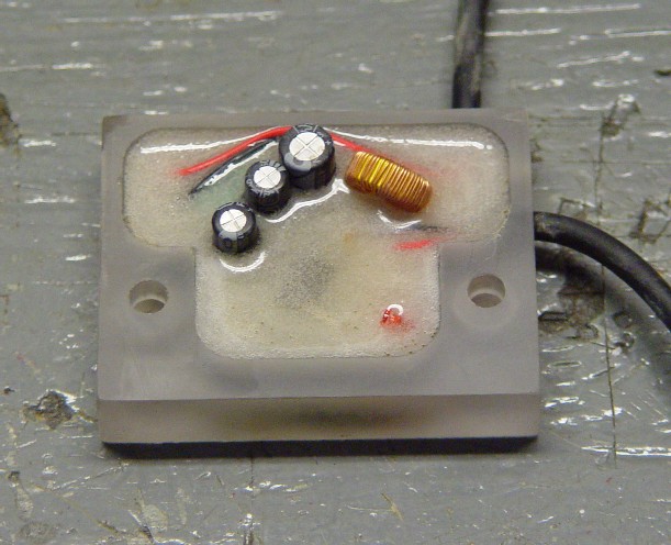
You now have four open solder pads on the circuit board. The 12V power in connects to VI+ and VI- (on the left in photo), and the 3.15V out connects to VO+ and VO- (on the right).
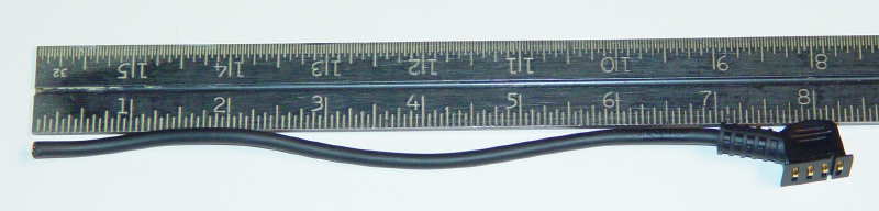
We will cut the original power cord and rewire it into these connections. Take the end of the cord with the eMap plug, and cut the cord about 7” from the base of the strain relief. NOTE: This assumes that you will be mounting the adapter block in the lower set of holes on the RAM mount. If you are using the upper holes, and mounting the ball in the lower set, you will need to cut the cord longer. You may also want to drill a hole for the cord on the other side of the block, so you can flip the block around.
Feed the wire through the lower hole on the right side of the housing block. You may have to twist it a bit to get it through:
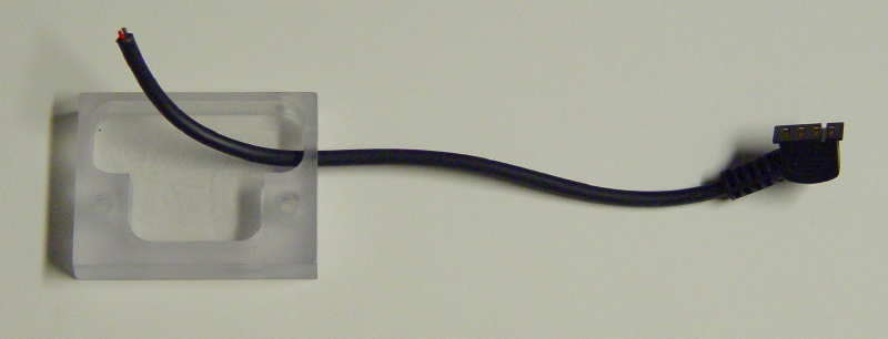
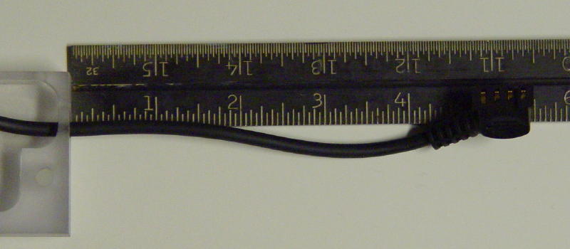
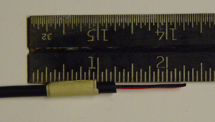
Adjust the length of the cable so that there is about 4-1/4" between the adapter housing and the end of the strain relief.
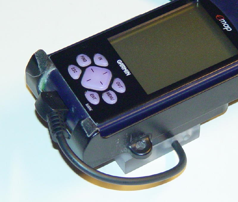
Place your Emap in your RAM mount, and place the adapter block underneath, aligning the mounting holes. Make sure you are comfortable with the amount of slack in the cord. You don't want a big loop that will get caught on things, but you don't want it so tight that there is strain on the wire. Adjust the cable length as necessary.
Wrap a piece of tape around the cable where it enters the housing to mark the length.
Remove the wire from the housing. Cut the end off at 1 Ľ” from the tape, remove 1” of the outer jacket, and strip 1/8” of insulation off of the ends of the two wires.
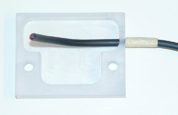
Remove the tape, and reinsert the wire into the lower hole on the adapter housing. You will need slack to solder the wires, so pull the wire through almost to the plug. Insert the red wire in the VI+ hole, and the black wire into the VI- hole. Solder the wires in place, and trim off the excess.
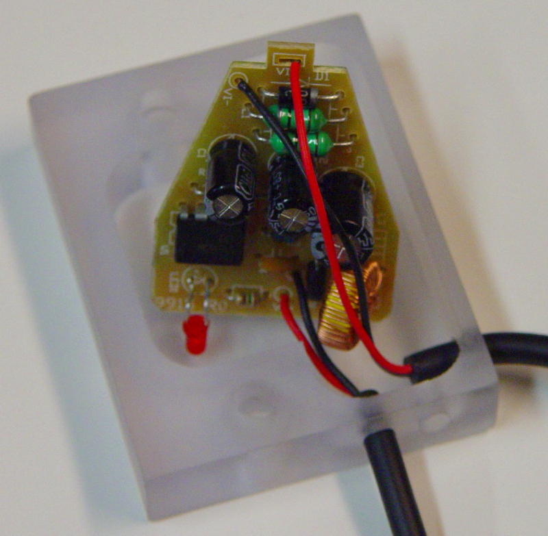
From the top side, you should have something like this:
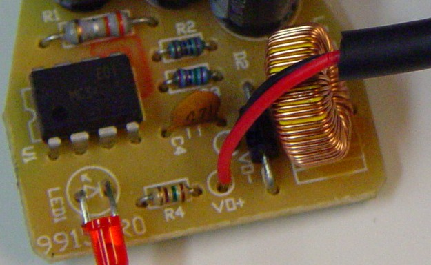
Take the left over length of power cable, and strip off 2-1/4" of the jacket. Strip the ends of the wires by 1/8".
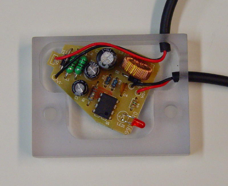
Insert the wire through either the top hole, or the upper side hole in the adapter block. The upper hole gives a more streamlined look in the end, but the wire comes close to the head on the RAM mounting ball screw. Test fit before making the final connections and decide which one you like better. The upper hole is used in the below example. Insert the red wire in the VI+ hole/slot, and the black wire in the VI- hole. Solder the wires in place, and trim the excess off of the bottom. You should wind up with this:
It is now time to secure the circuit board in the adapter housing. There is no turning back after this step, so test the adapter board to make sure that the wires are connected properly and the board didn’t get damaged during soldering. First, closely inspect the underside of the board and make sure that the power wires aren’t oversoldered, and are not shorted to adjacent tracks. Strip the free end of the supply wire, and connect to a 12V source. The power LED should light. Then, connect the unit to your eMap, and make sure it works. You may want to first measure the voltage across the power supply pins on the plug; they should read around 3.15V.
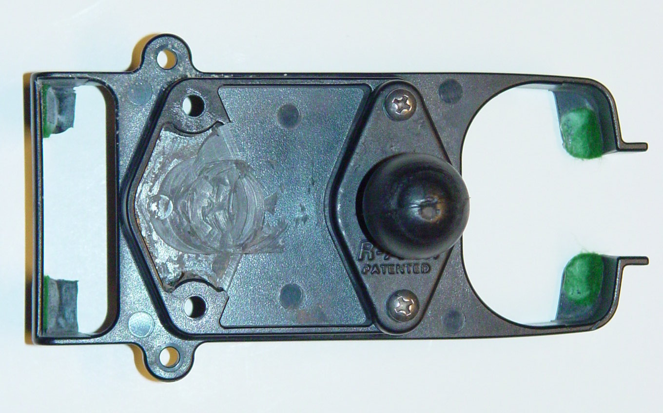
If the board checks out OK, mix up a small batch of 5-minute epoxy and pour it into the housing. Lay the circuit board flat in the housing, and hold it flat until the epoxy cures. Make sure you use a standard, transparent epoxy; any metal filling may conduct electricity and short out the board.
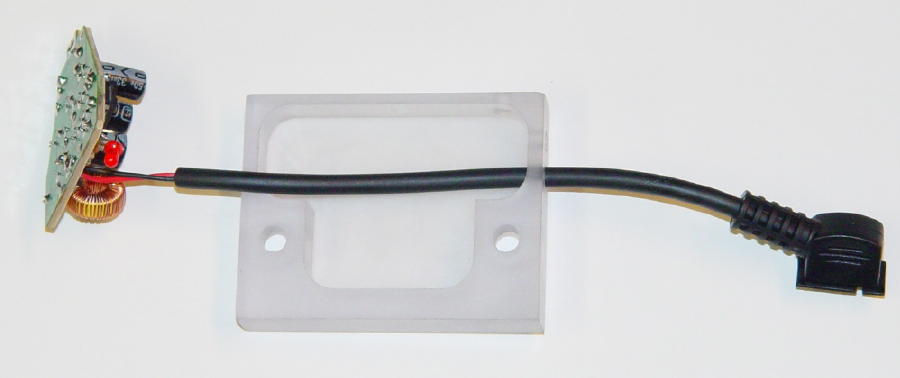
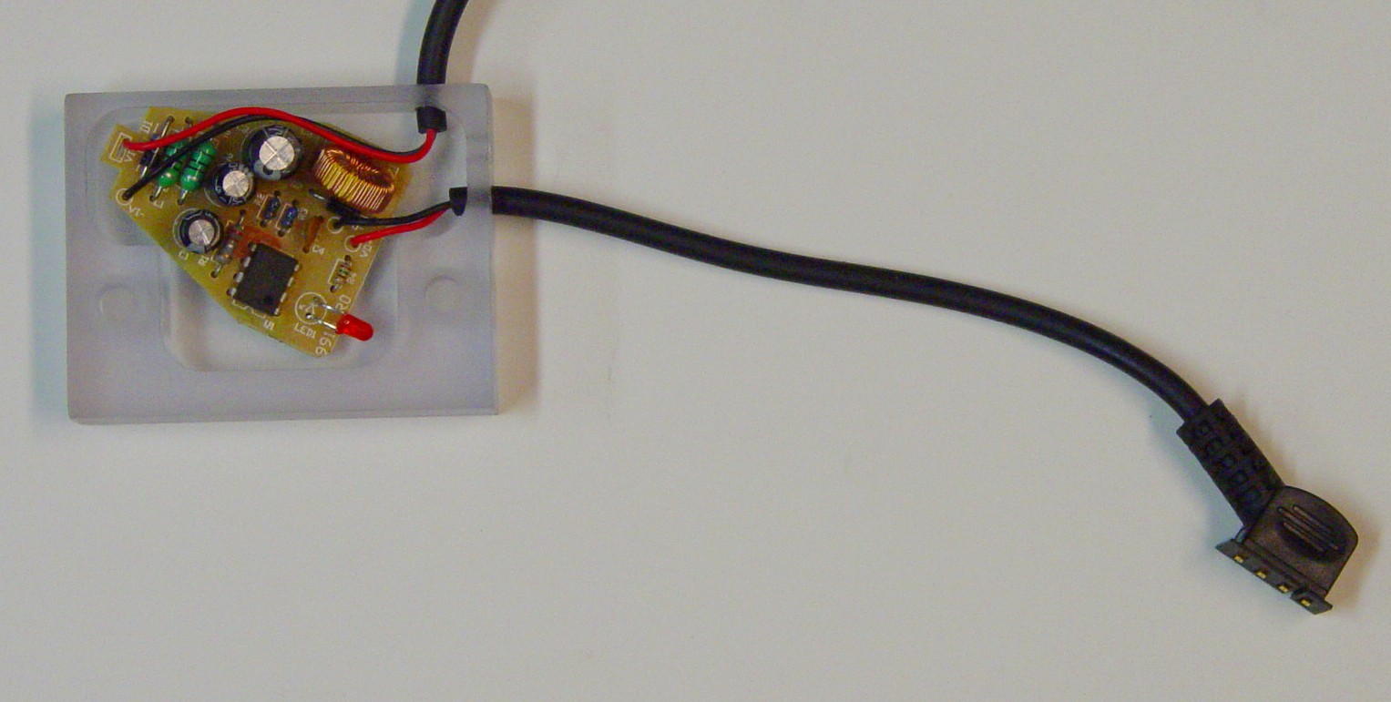
Next, we will pot the remainder of the circuit board in epoxy to protect it from water and vibration. Twist the output cable in its hole so that the plug faces downward, as shown in the photo below. (This will make it easier to line up with the socket in the eMap when plugging it in.) Don’t twist so much that you twist the wires out of their solder pads, though! Also, plug the unused power cable hole with masking tape so the epoxy doesn’t flow out while it is setting up.
It will take a lot of epoxy to pot the circuit board. I recommend an epoxy with a longer working time (like 2-ton epoxy), so it has time to flow into the corners, and some of the air bubbles can rise out. It's OK to do the potting in multiple batches; let each one cure for an hour or so before pouring the next one. You don't have to totally immerse the components, but all of the bare wires and leads on the board should be coated. Also be sure to get a good amount of epoxy on the large components, like the capacitors and especially the coil, to keep vibration from breaking their leads.
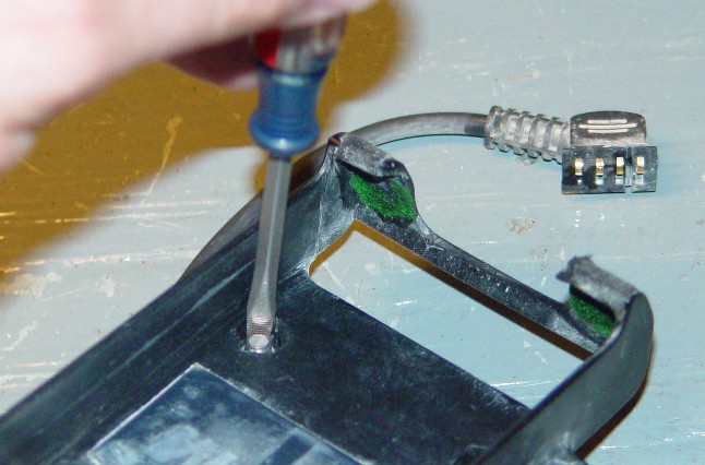
In order to mount the adapter block under the RAM mount, you will need to remove some of the reinforcing rib. The photo below shows it done sloppily with an end mill. (Hey, it was hard to grab the mount in the vise!) You may not have to remove the entire rib, so test fit and cut as needed. A rotary tool, diagonal cutters, or nibbler should be able to do the job. Be careful that you don't apply so much cutting force that you break the RAM mount.
Finally, it's time to attach the completed adapter block to the underside of the RAM mount. Insert the socket head screws into the counterbored holes in the block, and drop the nuts into the hex recesses in the RAM mount. (Probably easiest to do it one at a time.) You should be able to start the screws with no problem, but once they hit the nylon inserts in the nuts, the nuts will begin to spin. The RAM mount is designed for SAE hardware, but the adapter block is supplied with metric hardware to remain consistent with most of the bikes it will be used on. In order to keep the nut from spinning, wedge the blade of a small screwdriver between one face of the nut and the hole while tightening the screw.
Cut the 12V power cable to a convenient length for your setup and terminate it as you see fit. The connector shown on the Big Cee site is a Molex Mini-Fit Jr plug, which doesn't require a lot of force to connect/disconnect, but has a locking latch to keep things in place. They are available from Digi-Key, as well as other sources. Another option is the BMW-style mini plug, available from Powerlet. If you wish to swap the unit between your bike and four-wheeled vehicle, simply get an inline socket to match the plug, and connect it via a length of cable to a cigarette lighter plug.